

|
|
|
This document covers the most important technical concepts behind Camelot. It does not go into any detail. There are other documents around for that (hopefully). Test IntroductionThis document covers some of the more fundamental aspects of
Camelot. It is intended primarily to help new Camelot developers and is
presented as a list of potential questions & answers. Some of the
information provided here is aimed at people new to C++. Please skip
ahead if you know this stuff. This document covers the following areas: Data typesDesign fundamentals Objects & Memory Management Portability, The Oil / Kernel division Documents & The tree Coordinate Systems Paths & Transformations How documents are rendered Ops, Undo & Redo Messages Dialogs, Bars & Galleries Multiple Documents & Document states Blobs & the selector tool Tools Error & exception handling Writing code What are all these names?Camelot is the internal project name for the codebase that
produced the products; Xara Studio, CorelXARA, Xara X, Xara Xtreme and
Xara LX, and no doubt many more to come. ArtWorks was a forebear of Camelot. It was a popular drawing program on the Acorn RISC platform. Impression was another forebear of Camelot (but less directly). It was a Quark-like DTP package created for the Acorn RISC platform. As they sometimes say - build one to throw away and then build one
right. Camelot was a ground-up re-build using the experiences and
lessons learned from Impression and ArtWorks, and although very little
of the DTP heritage shows through to the end-user in today's Camelot,
the architecture is such that it could be turned into a more broad
DTP-like product. As a result you will find these design-notes refer to
some DTP features such as text stories, page spreads, chapters, etc. Is there anything else I should familiarise myself with?You should be able to read this document without having a full
knowledge of C++, but a rough idea of how object-oriented classes work
is invaluable in getting the most out of this document. There are many good primers available covering Object Oriented programming. Anything else that might be useful?Here's a screen shot of Camelot which explains what we call the
various bits of Window furniture. The bits of the document are
explained in the Rendering section. 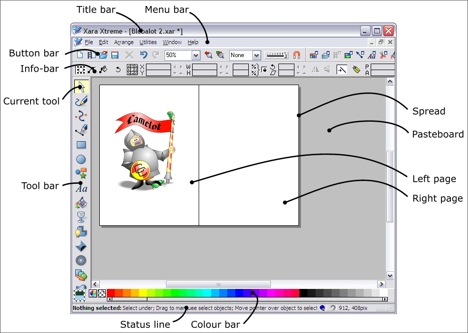 A spread is a collection of pages with an associated pasteboard around the pages. Internally the pasteboard is part of the spread, but the user may not perceive it this way as he/she sees the spread only as the pages involved. When zoomed out, and/or when there are spreads of different widths, then there may be an 'off paste area' to the right of the spread which is rendered as needed to fill up the window. Design fundamentalsThe design of Camelot is mainly aimed at making the program easy to use. That means:
Tools and modesTo help the user understand the program he should be able to build
a working model of how the program works (consciously or
subconsciously). The program should have no hidden modes which would
make the program behave differently without the user being able to see
why. Tools represent the major, visible modes of the program to the user with a large highlighted tool button, a unique info-bar and a different cursor shape. Button-up drags, where some graphical element remains attached to the cursor position while the user is not
holding a button down, are strongly discouraged - in fact there are
none in Camelot. Button-up drags are bad because they are a form of
hidden mode, they don't work well with pen-driven input and they always
leave the user wondering how to get out of the mode and whether their
changes will be retained or ignored at the end of the drag. WorkflowModeless editors, dialogs which allow the user to use the main program while they remain open, save the user from repeatedly opening and closing dialogs.Major functions are designed to take the least number of clicks to accomplish. Editing is done directly in the document wherever possible. Objects & Memory ManagementHow does memory management work under C++? Does memory move, for instance, once it's allocated?Camelot's design greatly exploits the object-oriented nature of
C++. Thus, with very few exceptions, all data within Camelot is
encapsulated in objects and very little use is made of global
variables. All of the memory management is done for you by C++ and the
basic Camelot object types. Once memory is allocated in this way, it is
always static. You will very rarely need to ask for a block of memory,
normally you just need to do new(Object). and everything will happen
automatically. Thus you never need to worry about subsequent allocation of memory moving other things around. In terms of memory address, data is scattered throughout logical address space. This means that there is little to be gained in having buffers full of continuous data. You might as well use a linked list of objects which are separately allocated. It also means that it is vitally important for you to keep track of memory allocations you have made, and free them at the appropriate point. With all of these objects scattered around memory, how do I keep track of them?Fortunately, C++ makes this easier for you. Most classes within
Camelot are derived from CCObject (or wxObject, the wxWidgets version).
CCObject is designed to provide extra functionality over vanilla
objects and to help with debugging. For instance, if you leave any such
objects lying around by mistake, Camelot will inform you of this when
you quit. It can also check the validity of new() and delete() calls. How on earth can static allocations be efficient?If you are used to large dynamic data structures, this may seem
strange to you. Firstly, all our objects (and thus allocation size) are
far smaller (on average) than each dynamic area allocation within a
program such as Impression. This means that though there are likely to
be many holes within memory, they are small. Also, we have far more
allocated objects within memory, and thus these holes quickly get
filled. Furthermore, virtual memory managers will free up any pages of
memory that contain no allocations and give this memory back to the
operating system so thatit may be used again (either by us, or by
another task). We benefit greatly from the fact that whenever we allocate memory in this manner, we do not have to move any memory about. This proved a bottleneck in ArtWorks which also had many small allocations being used concurrently. OK, so if all data is encapsulated, where do I put data I would have put in a global variable?Newcomers to object oriented design might find the lack of global
variables disconcerting. The first place where data should be stored is
encapsulated within a class (for instance as a class variable).
Remember, if the class you are thinking of using will have more than
one instance, but your variable needs to be common between each
instance, you can use a static member. The great proportion of
variables fall into this category. If data cannot be neatly encapsulated into another class then it can be put into the Application class (or sometimes the wxApp class). Anything else I should remember about C++?
Portability, The Oil / Kernel divisionTo what extent is Camelot portable?C++ is a portable language, and Camelot is written to be a
portable program. However, it must still deal with the operating system
(and to some extent, the processor), of the host machine for which it
is compiled. Different processors might be have different byte orders,
and/or have different OS interfaces. Compilers may have different sizes
of fundamental types. All of these differences have to be accomodated
in way that collects them all together and leaves the majority of the
code untouched when it is ported. How is portability achieved?Camelot divides the code up into two major sections; the Kernel
and the Oil (Operating-system Interface Layer). The kernel is that code
which is guaranteed to remain the same on any operating system or
platform. The Oil layer is that code which might change on a
different operating system or platform. Thus you should not make any
operating system calls whatever within the Kernel layer but you can
write general-purpose code in the Oil layer if you want (but it's best
not to). There is one set of Oil layer source code for each target
operating system API. The original Windows version of Camelot has an
extensive WinOil layer. The Open Source version currently only has a
wxOil layer which uses wxWidgets platform independent API. Camelot tries to use portable data types and tries not to assume
anything about byte ordering. Processor dependent code is put in a
specific sub-directory of the Oil layer (for instance INTEL for x86
processors). Thus to port to a different processor requires creating a new
processor dependent directory and re-implementing the small number of
maths routines it contains. To do a port to a different operating
system which wxWidgets supports should (theoretically) be just as easy.
To port to an operating system with a different API would involve
writing a whole new oil layer. This would be quite a substantial task. 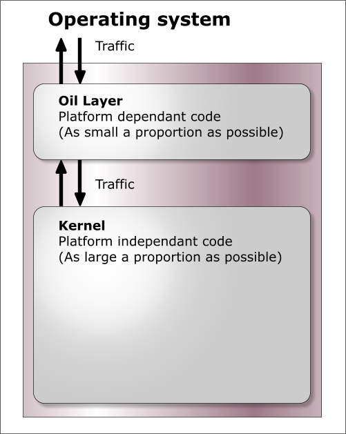 Documents & The TreeWhere is document data stored?Data relating to a single document (i.e. what would be saved) is
normally stored in "The Tree". There is one tree structure per
document. Each node in the tree could represent a tangible object
within the document (a shape, for instance), or a way of rendering
objects (an attribute), or perhaps something less tangible such as a
layer. Nodes share data items such as colours or bitmaps and so these
things are stored outside the tree in lists called DocComponents. Why a tree, and what is its structure?It's a tree because this is the data representation that best
satisfies our needs for speed and efficiency. The tree gives us many
advantages: to understand why you need to appreciate how attributes
work, how groups work, and how rendering works. The tree is made solely from nodes. Each node is an object, of a class derived from Node. Every node has a pointer to its parent node, to its previous and next sibling, and to its first child (left most node on the line immediately beneath on the diagram below). Any of these pointers may be null if there is not a node in that direction. 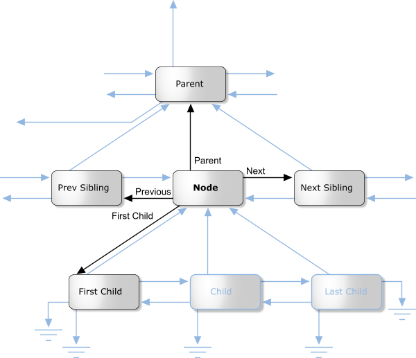 Of course, you don't need to worry about maintaining these pointers: the Node class does this all for you. For instance your constructor will allow you to build a node attached to any other node in any given direction. There are nodes for many things: Pages, spreads, attributes (things that affect the way other things are rendered, such as colours), ink objects (for instance paths), and layers all have classes derived from Node. Here is a class hierarchy for the Node class (don't confuse this with a tree diagram - they sometimes look similar). Note that this hierarchy is incomplete - this is (after all) a basic overview. But it is correct as far as it goes.  What about renderable nodes?The nodes concerned with rendering are shown below in their class hierarchy.  NodeRenderableBounded objects are entities such as pages, spreads, and the objects (lines, text etc.) on them (any object that has an XY bounding rectangle). These are divided into paper objects and ink objects (i.e. objects printed on a page). This is an important distinction. Paper objects are quite different to ink objects; they make up the structure on which the document is displayed, and aren't for instance rendered during printing. The ink objects are what the user would consider he/she had drawn. NodeAttribute objects are those that apply attributes to renderable ink objects. Examples of these are line colour, fill colour, line style, and so on. How are nodes arranged in the tree?We'll deal first with the top section of the tree. This mainly consists of paper objects.  The StartDocument, NodeDocument, and EndDocument nodes are there for 'technical reasons', and you shouldn't be concerned with them at this stage. The tree proper starts with the default attributes. Every attribute class must have an entry here, otherwise when an object needed to render itself, and it had not got an attribute of this type as a child, the object would not have a value of this attribute to use. Each chapter node has spread nodes as children, and each of these has pages, grids and layers (in that order) as its children. The ink objects are children of the layer on which they reside. What about ink objects? How do attributes in the tree affect the way things are rendered?All ink objects are children of a layer. They represent the meat of any document. Attributes are attached (as a child) to the object they affect (some form of NodeRenderableBounded). The attributes stack up, so that, for instance, a line colour attribute could be attached to a layer object, and then this defines the default line colour for that layer. Any objects on that layer will be rendered in this line colour, unless they have a line colour attribute specifically attached to them. This can work for groups too - a group may have an attribute attached to it; this will affect all objects in the group unless they too have an attribute attached to them to override it. As an example, the picture below consists of a red rectangle (with a black line colour), and a group containing the blue rectangle (with magenta line colour) and the magenta freehand path.  The diagram below shows how this would be represented in the Camelot document tree. You'll notice this diagram is drawn differently from the tree diagram we drew above. Some times it is more useful to draw siblings beneath each-other and signify a child by indentation. So in the diagram below, LineColAttr: Black is the first child of the layer node, and it's siblings are LineWidthAttr: 0.25pt, FillColAttr: Black, NodeGroup and NodeRect. It is perhaps unfortunate that there are two ways of drawing trees, but they both have their merits, and are both used extensively throughout Camelot documentation, so you should get used to them both! In this documentation, when I refer to 'left most', I'm talking about left most in the former sort of tree diagram, where siblings are pictured in a row, rather than in a column. If you don't like or don't understand this sort of diagram, have a quick look in the next section and you can see the equivalent diagram drawn the other way.  As can be seen from the diagram, attributes that apply to groups apply to all children of that group, unless overridden by other attributes. For example, all objects in the group are rendered with magenta lines 6pt wide - hence the NodePath appears as a magenta line. The NodeRect would be rendered with magenta line colour and black fill colour, but it has a child attribute specifying a blue fill colour, so the black colour is overridden. Similarly, if it had a blue line colour attribute, it would override the magenta line colour attribute of the group. How is the z-order stored? What about groups?The z-order (which objects are in front of which other objects) is
stored inherently in the tree structure. The whole tree is rendered
from first sibling (on the left or at the top, depending on your
representation) to the last sibling (bottom or right). Each time a node
is met which is a parent node (has some children), its child list is
rendered first sibling to last sibling, before the siblings of the
parent node itself are rendered. Groups are stored such that their members are children of NodeGroup (a class derived from NodeRenderableInk). Naturally, in any child list, the first sibling is the back-most object, and the last sibling the front-most object. The way in which child lists are traversed means that in any given child list, no other child lists intersects it's z-order. Thus the children of a group are all adjacent in z-order. No other object may interrupt the z-ordering of a group. On the diagram below, the numbers indicate the ink rendering order for the previous example. The paper will already have been rendered at this stage. 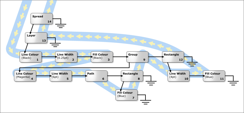 Where precisely do attributes go? What's all this about attribute optimisation?The way we described trees above didn't fully and uniquely specify
how attributes should be arranged to get any particular effect. This is
bad, not only because if people rampantly stuck attributes anywhere
they felt like, then the tree would not only become untidy, but would
also be overly large (also operations such as cut, copy & paste
would be subtly disrupted). Thus when attributes are applied, Camelot ensures, through a process called attribute optimisation, that all subtrees whose children have an attribute in common have this attribute stored as high up the tree as possible (the attribute becomes a left hand sibling of the subtree). This is in fact nothing to worry about. One of the fundamental rules of attribute optimisation is that it in no way affects what attributes are relevant to what objects (though it does, obviously, affect where they are stored in the tree). The following ten commandments of attribute placement describe the rules. They are enforced by the attribute optimiser. 1. If a particular subtree hath an attribute which is its offspring then this attribute will not appear anywhere else in the subtree, and therefore must be an attribute shared by all objects in the subtree. This convention allows us to determine easily those attributes which are common to all objects in the subtree. If for example a group object has a green fill colour child attribute then we will know that all objects in the group are green. 3. All left siblings of a node attribute are node attributes. This makes determining the common attributes of a subtree easy and quick. 3. If an attribute appears in a subtree then it must affect at least one object in the subtree. For example a Text attribute has no place as a child of a group which has only path objects as its children. 4. When a subtree is removed from a document it must not loose any of the attributes that it requires to render itself correctly. 5. The default attributes must be stored as children of the NodeDocument 6. There should be no superfluous attributes. An attribute is classed as superfluous if (a) It is overridden by an attribute (of the same class) before anything else has been rendered, or (b) an attribute which has already been defined. a. Select the red pen, Select the green pen, draw a circle b. Select the red pen, Draw a circle, Select the red pen, Draw a square 7-9 We haven't thought of these yet... 10. An attribute can be placed anywhere in the document tree, except where it conflicts with the other commandments. Attribute optimisation is something you probably don't need to worry about, even when designing attributes. You should bear in mind, however, that to implement commandments 4 & 6, the optimiser needs to be able to tell if two attributes have the same value. This is of relevance when you design your comparator method. What about hidden nodes?Hidden nodes are so frightening that you need to know very little about them at this stage! But here's a quick introduction: Hidden nodes are used as place-holders in the tree to implement undo. Thus, for instance, when a node or subtree is deleted, it's place is taken by a hidden node. This has a pointer in it (not the child pointer) to the nodes in question, which, of course, are not really deleted because otherwise you couldn't undo the deletion. Similarly, when you change the z-order of a node, a hidden node is inserted as a place-marker. Its hidden node pointer points to the node in its new position. Luckily, you shouldn't have to worry about hidden nodes, because there are Do functions (see later) which perform an Action (see later) to perform hiding and showing of nodes. These are called DoShowNode and DoHideNode. What ought not to go in the tree?Mainly things that don't have specific relevance to any node within it. Like lists of defined fill types for that document. Neither do bitmaps (for reasons of efficiency), nor will text stories (as they may flow through across multiple spreads). However, these will obviously be referenced by objects within the tree. How much work do nodes do?The node base class maintains everything common to all nodes (such
as the pointers to siblings, parents and children). The class specific
nodes are derived from (like NodeRenderableInk) will provide all the
functionality and virtual methods a specific node-derived class need
(we hope). All the derived node need do is implement these virtual
functions. This means that all the code for rendering a node can be encapsulated into the derived class. Thus nothing else need know about the internal data structure of a node object. For instance, the node will be called to render itself (see section on rendering), rather than the rendering system knowing anything about how each type of node is rendered. This is one of many examples of object orientation within Camelot. Coordinate SystemsWhy do we need different coordinate systems?There are several reasons. The operating system expects to be fed
coordinates as pixels. This depends on the scroll offsets and the zoom
factor we use. Because of this, it would obviously be impractical to
store coordinates of objects in terms of pixels. It would also be impractical to store coordinates of objects relative to anything except the spread on which they exist - if sufficient resolution was required, the coordinates would be very large and slow to get enough pages to work. Also inserting extra spreads would require substantial work changing the coordinates of every object. Limitations of the resolution and scope of coordinates force us to have a couple more. What coordinate systems exist within Camelot?The following co-ordinate systems are used in Camelot and each is explained in detail below. · Spread Co-ordinates - The position of the objects (such as lines and rectangles) are recorded in these. These are measured in millipoints (1/72000 inch) relative to the bottom left hand corner of each spread (which might not necessarily be the bottom left hand corner of the bottom left hand page, because of the paste area), and give each spread a maximum extent of about half a square mile. As a result of the large drawing area available to each spread we can let the user draw on any part of the window, even if we have a full screen view scaled to 5%. All the ink objects in the tree, such as NodePaths and NodeRectangles, have their co-ordinates stored in Spread co-ordinates. These are (apparently) similar to Impression coordinates except they are positive & relative to the bottom left corner (rather than negative & relative to the top left corner). · Document Co-ordinates - The positions of the chapters and the spreads in the chapters are all measured in Document Co-ordinates. Each chapter runs vertically down through the document space and all the chapters lie side by side. It will allow about 1000 pages per chapter and about 1000 chapters per document. These are measured in millipoints. None of the objects that can be drawn (e.g. paths, rectangles etc.) are represented in this co-ordinate space (just chapters & spreads). · Logical Co-ordinates - There is very little work is actually performed in Logical co-ordinates in Camelot as they only really exist in the middle of the transformation from Document Co-ordinates to Work Co-ordinates (thus they are never stored). Here the Y co-ordinates are 64 bit numbers so that all the chapters in the document can be stacked on top of each other to form a very tall and thin document. This is closer to the view that the user sees. These are measured in millipoints. You will rarely have to use these coordinates. · Work Co-ordinates - These are the same as Logical co-ordinates, only scaled to take account of the view scale factor. These are still notionally measured in millipoints, but obviously these are 'scaled' millipoints, i.e. only at 100% scale factor will these millipoints correspond to physical millipoints on screen. You will rarely have to use this coordinates. · Oil Co-ordinates - These are close to the co-ordinates used by the host operating system, but are still measured in millipoints, like Work coordinates. Oil co-ordinates are in fact just the same as Work co-ordinates, except the scroll offsets have been subtracted from them. You will rarely have to use these coordinates. Window Co-ordinates - These are actually the coordinates used by the host OS (at last!). In the case of MS-Windows, they are measured in pixels. Note that these are cunningly the other way up from the normal world's understanding of coordinates - on Windows as Y coordinates increase the pixels move further down the screen. So how does it work, for example how do we change the coordinates of an object in the tree to screen coordinates?To get an object to the screen it has to be transformed from the
Spread Co-ordinates that are held in the tree to the Oil Co-ordinates (sic - see below) that
can be rendered to the screen. Since the objects on each of the spreads
are stored in co-ordinates that are relative to the spread, we need a
separate transformation matrix for each spread. The following
transformations have to be performed for each spread : Translate from Spread Coords to Document Coords. i.e. Translate the coords from being relative to the spread, to being in the spread in Document Space. Translate from Document Coords to Logical Coords. i.e. Move the chapter down and across so that all the chapters are in a single column. Scale from Logical Coords to Work Coords. i.e. convert from millipoints to scaled millipoints by using the current Zoom factor. Translate from Work Coords to Oil Coords. i.e. translate the origin to the position of the scroll offsets. 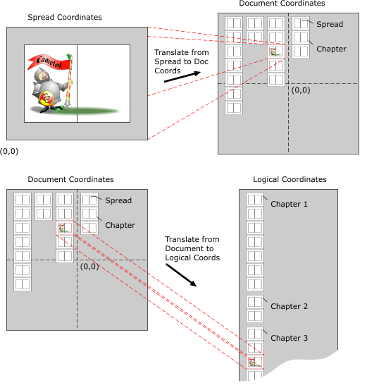 But isn't all this transformation incredibly slow?No. Camelot uses a single transformation matrix (well actually one
per spread) to do the whole transformation. It does this by composing
the transforms required between each system into a single matrix.
Clever, eh? Hang on, you forgot Windows coordinates in the example above, didn't you?Urrm... yes. Actually the final translation to pixels is done
separately within the oil layer as the matrices aren't accurate enough
to handle these. But this is done as close to the OS as is humanly
possible. Paths & TransformationsWhat is a path?Well, a path is essentially a line. A path is made up of a series
of straight line sections and curved line sections. It is the most
basic element used to build all almost all other shapes. For example, a
rectangle is a path that is made up from 4 straight line segments and
an ellipse is made up from 4 curved segments. These LineTo's and CurveTo's indicate how to draw lines between a series of (spread) coordinates. There is also a MoveTo element that tells us to Move the pen to a specific location without drawing anything. A sample path that draws a unit square at the origin is described below: MoveTo 0, 0 (Move the pen to the Origin) LineTo 1, 0 (Draw a line from the current position (0,0) to 1,0) LineTo 1, 1 (Draw a line from 1,0 to 1,1) LineTo 0, 1 (Draw a line from 1,1 to 0,1) LineTo 0, 0 (Draw a line back to the origin) How is the path data stored?The path's data is in the Path class. The path class uses the
dynamic heap to store the paths data. As elements are added to the
path, this area grows, and as they are removed from the path, the area
shrinks. Each coordinate in the path has an associated Verb (MoveTo, LineTo etc.) as well as an associated Flag which holds extra information about the coordinate (such as if it is Smoothed). External to the Path Class these 3 separate sections of data appear as 3 arrays. An Array of Verbs, an array of Coordinates and an array of Flags. The path class can be asked for the location of any or all of these arrays. CurveTo elements require 3 coordinates to represent a complete curve and each of these coordinates will have a CurveTo verb and its own Flag. For example, a path containing a single bezier curve would look something like this :-
The paths can contain sub-paths, separated by MoveTo elements as in postscript. The paths data is stored in an identical fashion to that used by NT. Under Win32 it is possible to get NT to render our paths simply by passing it pointers to the Verb and Coordinate arrays. How do I use paths?The path class refers to positions in the path by its slot number.
A slot is a single coordinate. The path described in the table above
contains 4 slots (one containing the MoveTo and 3 containing CurveTos).
The path is happy to let you know how many slots it uses by using the
function GetNumSlots(). Each of the three sets of data (Verbs, Coords and Flags) can also be accessed by asking the path. The functions GetVerbArray(), GetCoordArray() and GetFlagArray() will return you pointers to these arrays. Note that these are pointers to objects which are allocated dynamically, so they must not be stored. You should use the Get???Array() functions as close to the point where you need to use the array as possible, and not preserve their return values across calls to functions which might move memory (see the section on memory management for more details). For example, here is a function that look through the path to see if any of the sub paths start at the coordinate supplied - it's just an example, so it does nothing useful. LookAtPath(Path* pPath, DocCoord ClickPos) { // Find out how many slots there are in the path int NumSlots = pPath->GetNumSlots(); // Go though the path for (int I=0; i<NumSlots; I++) { // Is this slot a MoveTo if ((pPath->GetVerbArray())[i] == PT_MOVETO) { // Yep, does the coord at this slot match the one supplied if ((pPath->GetCoordArray())[i] == ClickPos) { // This subpath starts at the coord passed in // do stuff here.... // It's OK for this bit to move memory as we haven't // stored any pointers to the arrays. } } } } You can use these arrays to modify and examine the contents of a
path, but if you need to insert elements into the path you must use the
supplied Insert...() functions. These deal with all the memory
allocation problems, moving sections of the path apart and maintain the
consistency of the path. The insert functions make use of a current
insertion point which must be set (using SetPathPosition(LONG) ) before
performing the insertion. You are then safe to call one of the
Insert...() functions. What are transformations?A transformation is something which can be applied to a node
within the tree which alters its 'spacial characteristics'. They are
best illustrated by example. There are two sorts of transformation -
simple ones that can be applied by a matrix and complex ones that are
applied algorithmically. Simple transforms are things like: Scale, Stretch, Skew, Rotate, etc., etc. Complex transforms are things like: Envelope, Perspective, maybe Extrude, etc. These two types of transform also have very different ways of recording their undo information. Simple transforms are "invertable" - their inverse matrix will undo the operation. Complex transforms are "non-invertable" - to undo these operations the original data must be stored. How is can an arbitrary transformation be applied to an arbitrary object?In Camelot we are striving for the ideal case where every
transformation can be applied to every type of object! Obviously, this
is not possible in some cases but we are not going to use difficulty as
an excuse to cop out of transforming the more exotic objects (lack of
time, maybe!). When your node is transformed its Transform function is called and is passed a reference to a Transform object. This object contains the functions and data needed to transform any coordinates in your node. All your Transform function needs to do is get an array of SpreadCoords ready and pass them to the appropriate function in the Transform object. It will "pass you back" transformed coordinates. This works for both simple and complex transforms. Many complex transforms can really only be applied to paths and so before a Complex transform is applied, all the selected Nodes are asked whether they need to become paths for the transform to work. This is done by the "make-shapes" system. Make-shapes is a system which requests nodes in the tree to fundamentally change their formats. It is mainly used to request nodes to become path nodes but in future it could be used to change nodes into any other format (such as bitmaps, maybe). So, when you are implementing a class derived from Node think about whether your node can transform itself simply or whether it will have to turn itself into path nodes. Note that the user has direct access to the make-shapes system through the "Convert to shapes" OpDescriptor (see section on Ops) so you'll have to be prepared to turn your node into paths even if you can be transformed simply. How documents are renderedWhat do you call the bits of the document that get rendered?This is what we call the various rendered bits of a Camelot document: 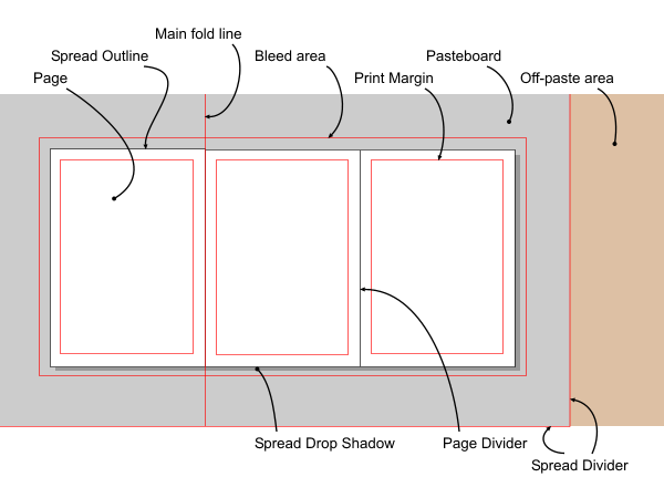 Why is rendering more complicated than just calling the OS to draw to the screen?We need to be platform independent, fast, support asynchronous
invalidation and redrawing, support background redraw (interruptable
& restartable rendering), and cope with merging of invalid regions. We also need be able to render as many objects as possible in one pass (a spread is the limit due to the coordinate system), and merge regions intelligently using fuzzy logic to cut down the number of invalid render regions active at any one time (and hence speed up rendering). Furthermore, we need to be able to render to a variety of different devices (contexts), such as: · Document view windows · Off-screen bitmaps (e.g. for use by CDraw's rendering primitives) · Click-detection bitmap · Metafile How is this achieved?We do this using RenderRegion objects, each of which represents a
region that is invalid and which must be redrawn. It contains state
information necessary to perform rendering, such as how far through the
document tree rendering has proceeded, the attribute context (line
colour, line style etc.), the area of the document to redraw, and so on. The RenderRegion object provides drawing functions for the renderable objects to call. Thus when an object in the tree, such as a path, is asked to render itself, it may call functions to set the line colour or width, and functions to draw a series of line or curve segments. In other words, the invalid region (render region) provides the primitives to validate (render) itself - object orientation in action! The render region knows which DocView object (a kernel representation of each view opened in Camelot) it is attached to, and which Spread object it is rendering. It also contains a matrix which converts the co-ordinates of a renderable object into the coordinates to pass to the OS rendering primitives. What are the different types of RenderRegion?The class RenderRegion provides a base class from which to derive
real render region classes. At present Camelot uses OSRenderRegions for
host OS rendering (e.g. Windows GDI, wxWidgets primitives), and
GRenderRegions for CDraw. How are these kept track of?Camelot maintains a single application-wide list of pending render
regions. This is implemented by the RenderRegionList class. This list
is scanned on timer/idle events, and a region is rendered for one
timeslice before returning control to the OS. In this way background
rendering is achieved without using multi-threading (but that might be
better). This class has special functions for adding a region to a list - these functions perform fuzzy merging, discard redundant render regions, and ensure that no two render regions overlap. When a RenderRegion object has finished rendering - i.e. its region is now valid, it is removed from the list and deleted. How does rendering take place?We will assume we start with a region the host OS considers
invalid. It passes a redraw request (under Windows an OnDraw message)
to the application which is received by CCamView. This, in turn,
extracts the region list from the message, and processes each region in
turn by converting its coordinates to OilCoords and passing them, along
with the Device Context, to DocView::OnDraw. DocView::OnDraw determines which chapters, and then which spreads intersect with the invalid region. For each of these regions, a render region is created. This contains a matrix to transform the work coordinates held in renderable ink nodes to those needed for the destination device, and a clipping rectangle. The render region is then added to the global region list. The render region is started up by calling DocView::RenderView on it. This causes all the paper objects to be rendered, but no ink objects. When all the required render regions have been made, if immediate rendering is required, then Camelot.ImmediateRender is called to completely render all the render regions associated with this DocView. This causes all the ink objects to be rendered. The reason the paper and ink rendering is scheduled this way is that the whole DocView has paper/pasteboard rendered immediately, which looks much better than each spread rendering its paper and ink in one go, leaving the other spreads containing whatever garbage happened to be on screen at the time, until it has finished. So how do the ink objects get rendered?DocView::RenderView is called once for immediate render regions,
but multiple times for background render regions (from a timer). It
renders the paper (the first time, unless printing), and loops to find
ink objects, only rendering those whose bounds intersect the clipping
rectangle. The loop terminates when the next node is NULL, or the
CanContinue function returns FALSE. The latter occurs when background
rendering, and the timeslice has been used up. For each node, Node::Render is called. This is a virtual function which is over-ridden for different node types such as LineColAttr, NodePath, NodeRect and so on, to call the relevant rendering primitives supplied by the RenderRegion class. Note that ink nodes and attributes are rendered in exactly the same way at this level (but they do different things internally). So how do strike providers & fill providers work?Camelot has an extensible system of fill and stroke providers
which allow us and third parties to provide new ways of filling and
stroking paths. Detail of these is beyond the scope of this document. How to multiple views work?Each document maintains a list of all the Views associated with
it. When you invalidate a region you use InvalidateRegionAction which
takes a range of nodes (whose positions are stored in spread
coordinates). This invalidates the regions in all views. So OnPaint messages (equivalent to Wimp_RedrawWindow on RiscOS)
will be generated for each view intersecting the invalidated area, and
one (or more) RenderRegions will be created for each of these. There
are also some blob implications (see below). What about blobs and EORed renderingBlobs are anything that
needs to be temporarilly rendered into a view and is not a permanent
part of the document. They are usually used to show the user
information about the current editing state. Blobs are currently
rendered using an EOR ("Exclusive Or") logical operation so that they
can be removed quickly without having to re-render the document
undeneath because that could be very slow. As the final operation of rendering a DocView,
DocView::RenderOnTop is called. This returns a render region and starts
an 'On Top' rendering loop. On Top simply means that the rendering will
be done directly over the top of anything else that happens to be
there, without causing a redraw from the bottom of the tree (we've
already done that bit!). This function's main use is drawing on the EOR
blobs (for instance selection blobs, tool blobs, and those that are
there to show a drag is in progress), though it also can be used to
render these to a bitmap for click detection. Because these render regions are 'on top' of the others, EORing can take place. This function is also called to add & remove blobs without redrawing the document. The actual drawing is done by the nodes in the tree concerned, in conjunction with the blob manager. This is covered under the section on blobs & the selector tool below. Ops, Undo & RedoWhat are Ops?In Camelot we have a class of objects that represent the
interactions between the user and the program. These are called
Operation objects (i.e. objects derived from the class Operation). An
Operation (or Op for short) encapsulates all the code that carries out
some action(s) that the user has asked the program to do. The Operation class implements the aspects of interacting with the user that are common to all operations and each of its derived classes represent a single interaction with the user (this is a simplification of the actual class hierarchy!). Every operation that the user can perform in Camelot, whether it works on a document or just modifies some program data, must be implemented by a specially-written class derived from Operation. What advantages does coding using operations give Camelot?By coding these interactions as objects all of the Op type they
all have a consistent programming interface, making it easy to connect
to the menu and hotkey systems and opening up the possibility for
external programs to call them (but the parameter lists for some Ops
are a stumbling block). Operations can call each other in a
well-defined way. Operation objects can be placed in a list to
implement undo & redo - indeed operations are fundamental to the
undo system. Operations can model long-lived user interactions with the
user such as dragging and dialog boxes. How are operations represented to the user?The OpDescriptor class and its derived classes describe the
Operations. The descriptions that OpDescriptors provide are used to
make Operations visible to the system and the user. The descriptions
may describe menu items, hot-key presses, buttons on a button-bar or
keywords in a control language - or any combination of these. What kinds of operation are there?There are two main types of operation in Camelot. Those operations
which can be undone and redone, and those which cannot. The first type
of operations usually affect the document in some way, and so need to
be undoable so that work can be restored. The second type of operations
are those which either cannot be undone for practical reasons (like the
file deletion operation), or operations which have no affect on the
document. Operations can be short-lived or long-lived.
While an Operation is doing its job it is "live" and can receive
messages. These messages report important events in the program such as
documents or windows opening and closing, the selection changing, etc.,
etc... When an Operation has completed its job it is added to the top
of the undo list (if it's undoable) where it is no longer "live" but
sort of "hibernating" - it doesn't receive messages until it is woken
up again to undo everything it did. How does undo / redo work?In Camelot all operations which are undo-able are stored in an
OperationHistory which contains a list of operations ordered
chronologically. The OperationHistory has a 'Now' pointer which points
to the last operation performed at the current time: all Operations to
the left of and including the Now pointer are operations performed in
the past, and are undoable.; all operations to the right of the Now
pointer are operations which can be performed in the future and are
redoable. When the Now pointer is NULL this means that no undoable
operations exist, if any redoable operations exist then the first can
be found at the head of the operations list. The size of the UNDO system in Camelot is user-adjustable, though it will probably be infinite by default. The Operation History keeps track of its current size, and the maximum size that it should be allowed to grow to. There is special logic in Camelot to get rid of old Undo records when memory is running out.  Since an operation might consist of many discrete actions (like individually changing many nodes), the undo system is made up of objects which are derived from Action. (Note actions are not derived classes of operation - each operation has lists of actions associated with it). These actions are strung together in a list, so that when the operation comes to be undone, all Camelot has to do is go through the list of actions, and execute them. Redo is handled because when each action is executed, it will build the required Redo action, and attach that action to the redo list.  Thus, there are possibly three different bits of code necessary for an operation: The code that actually does the operation, the code that undoes it, and the code that redoes it. Sometimes, the same code can be used to redo as undo (like changing some data in a node), and sometimes there are two complementary actions (like insert and delete). Redo and do are always similar (but not necessarily identical) code. This is for technical reasons. So do I have to create new Actions each time a want to create a new Op?No, this would be reinventing the wheel. Camelot provides several
'Do' functions (like DoMoveNode which moves a node in the tree) and
ready built Action classes like TransformNodeAction which applies a
transformation to a node (though there's DoTransformNode which is a do
function for this). There are other in-built Do functions for hiding
& showing nodes (hiding nodes is how we implement what the user
sees as delete), and many other common things. Of course if your Op
does something not covered by these, then you will have to create at
least one custom-designed Action. But most of the leg-work will have
been done for you. For a list of Do functions, see UNDOOPS.H. But I'm probably going to have to create an Op or an Action of my own sometime, aren't I?Yes. Obviously not everything comes for free. MessagesWhy do we have messages?Subsystems within Camelot may change parts of the system state
which other subsystems may need to know about. It would be foolish for
the subsystem making a change to some data structure to have to know
about all subsystems that would be interested in knowing about the
change, thus messages pass such information between subsystems without
the sender needing to know any details about the recipient(s). So when are messages used, and what are they used for?Messages are used for changes in system state, changes in document
state; the dialog manager also uses messages to convey user interaction
with gadgets in dialogs to the dialog's kernel representation. Lets take an example: When one of the indexed colours is changed by the colour manager, it broadcasts a ColourChangingMsg. The colour bar picks this up and knows to redraw bits of itself. If another subsystem were added (for instance a colour mixer), then it could listen for the same broadcast and no code in the colour manager would have to change. Messages make encapsulation (one of the principles of Object Oriented Programming) much easier. In the example above, for instance, the colour manager needs only to manage colours; it does not need to know which other parts of the program use them. All classes which receive any messages (derived from MessageHandler - see below), receive broadcasts which are perhaps the most important messages. They must filter out any that they are not interested in (like service calls or Wimp_SendMessage broadcasts under RiscOS). We don't send broadcast messages around in Camelot at every opportunity (as that would obviously slow the program down). Most broadcast messages are issued when a subsystem changes some piece of data that other subsystems will be interested in, like the colour change message above. Another important message is the DocChangingMsg which is issues whenever the selected document changes (see the section on Multiple documents and document states for more detail). One of the users of non-broadcast messages (sent to a particular class) is the dialog manager. This sends messages to the kernel code that runs dialog boxes (see the sections on dialogs) to inform them of clicks on controls within them. How do objects receive messages?The MessageHandler class is the heart of Camelot's messaging
system. All objects which need to respond to system messages are
derived from the MessageHandler class. When a MessageHandler object (or an object derived from MessageHandler) is constructed it gets added to a static list within the MessageHandler class. When a message needs to be sent to the MessageHandlers, the MessageHandler::Broadcast method gets called. This zips along the list of message handlers in its lists and calls their virtual Message functions. Each MessageHandler responds to messages it receives by handling the message in its Message function. To improve the efficiency of message handling handlers can declare themselves to be member of a particular group of message handlers and messages can be targetted at specific groups. These class groups must be pre-registered using the static MessageHandler::RegisterClassGroup method. For example, messages generated by the dialog manager need only be sent to DialogOp message handlers. Do they always get passed on to all possible recipients?No. Some messages can be 'eaten' to prevent them being passed to
any other message handlers. The message handler can return three
states, OK (if everything went fine), Fail (if memory runs out or the
message could not be processed for some other reason), or Eat (to stop
the message being passed on further). For instance, if the message is
one detailing interaction with a gadget in a dialog, the dialog taking
responsibility for that gadget will call a macro called EAT_IF_HUNGRY.
This returns Eat unless the message was sent to all gadgets (for
instance the close message when the application is shut down). The
other main use is in OpDescriptors (see the section on Ops) which claim
the message if they process it. Most other messages in Camelot should never be claimed. You normally do not need to worry about claiming messages as when you make yourself a dialog, you will copy the few lines making up the bare bones of the message handler from another dialog, and this does all the work for you. The same applies to OpDescriptors. How do I broadcast messages?The easiest way is to use a couple of Macros which make broadcasting much easier: BROADCAST_TO_ALL(Msg) BROADCAST_TO_CLASS(Message, Class) The second form lets you broadcast only to those objects which are a derived from the class you pass in. The message handler is also called directly in some rare circumstances. Normally, if you want to do this you shouldn't be using a message. How do I handle messages?When a message is sent to a MessageHandler object it arrives at the virtual Message function virtual MsgResult Message(Msg* Msg); In this function you determine the type of the message using IsKindOf e.g. If(Msg->IsKindOf(DialogMsg)) { DialogMsg* DlgMsg = (DialogMsg*)Msg; // Process the message here } This is quite powerful because you can create Major/Minor message codes by deriving classes from Message. E.g. You could have a Msg called DocMessage and then a number of derived classes of DocMessage: DocChangedMessage, DocDeletedMessage, etc. Dialogs, Bars & GalleriesWhy are dialogs Ops?Dialogs are invoked by the user clicking on a button within a bar,
selecting a menu option, or hitting a key shortcut. They are a classic
example of a user interaction with the program - exactly what Ops were
designed to model. They must also disable themselves at certain times
(and their menu options must grey out). As operations provide this
functionality, we made dialogs operations. Dialogs can only ever be non-undoable operations (for technical reasons); they can, however, invoke other operations which are undoable. How do user interface actions get to the dialog?This is done through messages. All dialogs are derived from
DialogOp, and DialogOp is a derived class of MessageHandler. All
relevant UI actions are transformed by the dialog manager into platform
independent messages. You need only respond to these. Most dialogs in
Camelot have no representation outside the kernel. Why don't most dialogs in Camelot have OK or Cancel buttons?Answer #1Most dialogs in Camelot are direct action dialogs. This means as
soon as you change something in the dialog, the page is affected. Thus
you never need to press OK, you merely need to close the dialog. Of
course, if the user decides he doesn't like his changes, he/she can
simply hit undo. All such dialogs are non-modal (you can do other
things while the dialog is up). This is an important standard within
Camelot. There are some dialogs which are modal (like 'File picture.xar already exists; do you want to overwrite it?'). These act deliberately differently. The UI guidelines restrict these to error boxes, warning boxes, and confirmation boxes. You don't need to worry about the difference though - all of this is handled by setting a flag to say whether you want your dialog box modal or not. Answer #2One of Xara's policies is to always make action buttons in dialogs
use words that directly relate to what the button will do when clicked.
This makes their action clearer to the user and makes it easier to
phrase the question or message in the dialog. How do I use the dialog manager?The best thing is to learn by example. To create a new dialog, the best thing to do is to copy an existing one. TOOLDLG.CPP & TOOLDLG.H are the recommended files. It's also worth looking at DLGTYPES.H which lists the various gadget messages. NewDlg.html describes the procedure of creating a new dialog in more detail. How do I use bars (put buttons on them, make new ones)?Windows version:To change/create a bar you edit Camelot's bars.ini file. At
present, this gets bound into Camelot as part of its resources; on
release builds, Camelot will read some proportion of the information
from an external file. You can make a new bar, or put buttons on
existing bars with no restrictions, and without any additional code.
However, you have to restrict yourself to using resource tags defined
in a .rc file. Your induction course will cover these in more detail. Here is an example bar definition in bars.ini: Bar "MyBar" Top 0 -1 Control H "Delete" 0 IDD_BARCONTROLSTORE IDC_BTN_DELETE V "Delete" 0 IDD_BARCONTROLSTORE IDC_BTN_DELETE Control H "ZoomCombo" 0 IDD_BARCONTROLSTORE IDCB_ZOOM_COMBO_BOX V "ZoomCombo" 0 IDD_BARCONTROLSTORE IDC_BTN_ZOOM EndBar The first line specifies that you want a bar named 'MyBar' which is initially to appear in the top docking bar in slot -1. The Control definition specifies that when the control is horizontal (H) it should be associated with the operation identified by the OpToken "Delete" . The fields following this specify where the controls resource is to be found (Module 0, Dialog IDD_BARCONTROLSTORE, control IDC_BTN_DELETE). The third line specifies the Operation and control for when the bar goes vertical. Because the Delete operation requires no parameters, it appears as a button regardless of the bars orientation. However the zoom operation for example requires a ComboBox (to enter the zoom factor) when the bar is horizontal, but when the bar goes vertical there is no room for the combo, so the control must change to a button which opens a dialog. This is the reason why a horizontal and vertical (Operation, Control) pair must be supplied. wxWidgets version:Right now, bar contents are not reconfigurable. They are just like dialogs, loaded from the XRC files. However, the XRC files are (outside the main build system) programmatically converted from the original .ini file by a nasty bit of perl. They are so similar to dialogs that the kernel bar classes currently do just about nothing, but you should use them anyway if you are making bars, as DialogManager looks at the RTTI information to work out how they should be handled.
Bar positions are reconfigurable. Bar docking is managed by wxAUI (in the wxXtra section). What are galleries?Galleries are merely glorified dialogs that always contain a list
box, and are resizeable. They are intended to present a list of
available items (each with a graphical representation) to the user, and
this list may be sorted in a number of different ways. Thus they
exhibit some user interface operations in common, and by deriving your
box from Gallery rather than DialogOp, you get most of this for free. Multiple Documents & Document statesHow does Camelot deal with multiple documents?Quite simply by having more than one tree (and thus more than one
NodeDocument), more than one Kernel Document object. The oil layer may
also have a representation of a document, but we won't go into that
here. Instead of always passing around a pointer to the document we wish the method we are calling to affect (which would be cumbersome), we maintain two document states, Current and Selected. The vast majority of the code should use the Current document by calling Document::GetCurrent(). The Current state is automatically set up to refer to the Selected document or other documents by event handlers. There is also a third 'pseudo-state' called 'the active document'. This is a state recorded by the operating system which is so similar to selected that you need not worry about it. What are document states?Documents have states which they enter and leave. As they enter
and leave some of those states messages will be sent describing the
transitions to the rest of the program. The two states used by Camelot are: Selected: records which document the user is working on and doesn't change very often. Current: records which document the program is working on and changes frequently. Putting the documents into states has the following advantages:
In ArtWorks the current and selected documents were recorded in
global pointers. In Camelot, these are frowned upon as being
insufficiently object oriented. Instead, the document objects make
themselves Current and Selected. This is a classic example of the
differences between procedural and object oriented programming. What does the selected state mean?The most obvious state that a document can be in is that it is the
document being used by the user. Only one document can be in this state
at a time and this state is called "Selected" because there are
(usually) visibly selected objects in it. Note that under Windows we follow the Windows guidelines that the object selection state is 'remembered' for non-selected documents, and that the first click in a non-selected document is absorbed and the selection state 'restored'. However, we don't actually remember the selection state, we just don't render the selection blobs in non-selected documents. Thus technically speaking, the selected document is the only document whose selection blobs (if any) we would render. How does this relate to the Active document?A document can also be Active, which means it has input focus and
any hot-key operations which apply to a document will affect the Active
document. There can only be one Active document at a time. In Camelot, the Active state follows the Selected state. It is not possible to have an Active document that is not Selected. However, it is possible to have a Selected document that is not Active. This is the situation when input focus has been switched to another application altogether, for example. (The Document containing the selected objects before we lost input focus still has those selected objects and is thus still in the Selected state but the input focus is now in another application.) This is a very subtle point and most programmers will never need to know whether documents are Active or not - they can rely on Selection. At the moment the Active state is not recorded directly in our internal data structures. We rely on the Operating System to record this information for us. Thus this is not a really a state in the same way as Current & Selected are. What does the current state mean?Camelot is an event driven program. It will receive events at any
time relating to any of the documents currently loaded. We cannot
predict which document, if any, an event will refer to ahead of time.
The event handlers set the Current state so that the rest of the
program knows which document any event is directed at. There can only
be one Current doc at a time. The Current state is only valid for the
duration of an event and sometimes changes during the handling of an
event. Current is just a temporary working variable that makes life
easier for the program. It is only "in scope" while an event is being
handled. The "event handlers" described above are not well-defined in
Camelot because of the way the Oil layer is implemented (either using
MFC or wxWidgets). There is always Oil layer code between the place
where the application receives the raw event from the OS and the place
where Camelot's kernel code gets control. In this context an "event
handler" is the earliest piece of Camelot kernel code that is called
from the Oil layer. The term Current is slightly confusing because the user sometimes
refers to the "current document" when he means the Selected one. A
better term for the document we are working on might be, "Working
Document", or "Event-target Document" but it will remain "Current" for
historical reasons. The Current document may refer to any of the loaded documents, including the clipboard document. Often the Current document will also be the Selected document but not always! Take rendering events for example. When the Camelot main frame window is maximised all document views in it will be sent requests to redraw themselves but only one of those will be the Selected document. For each redraw event received the redraw event handler in Camelot will set the Current document to be the one referred to in the event. Note that some events are not directed at Documents or views onto
Documents - they may be directed at the application as a whole. In this
case the event handler will probably either set Current to NULL or set
it to all loaded documents in turn, calling some function for each one. Is there any relationship between Current and Selected?No:
Note that the above assertions are true generally but within the
scope of certain event handlers they are more restricted. For instance,
in the rendering event handler, Current must be set to refer to a
particular document otherwise it just won't work. You can't make assumptions about the Current state based on the
Selected state and vice-versa. However, you can make assumptions about
the Current and Selected states based on the event you are handling and
so, for instance, it would be OK to ENSURE that Current is non-NULL in
a rendering event handler. What happens when the Selected document changes?It is important that other parts of the program are informed when
the Selected document changes and so the following DocChangingMsg
(subreason SelectionChanging) messages are sent:
What happens when the Active document changes?The Active state is encoded by the OS, not by Camelot, and because it closely follows the Selected state no messages will be sent when it changes. What happens when the Current document changes?The Current state is a temporary state for the convenience of the
program which can potentially change for every event that the program
receives. Routines in the program should make no assumptions about
which document is Current because of its transient nature and so they
shouldn't need to know when the Current document changes. It would also
be time-consuming to send a message every time the Current document was
set. So, no messages are sent when the Current state changes. When should I use Current & when should I use Selected?This problem is a bit of an old chestnut within Xara. Use Current whenever your routine might be called by some other part of the program. Even if you can't imagine your routine being used by anyone else at the moment, there is every chance that it will be one day so use Current in preference to Selected wherever possible. Use Selected if you know, absolutely 100% guaranteed, that your
routine will only ever refer to the Selected document or if you are
top-level event handler. If this is the case then you should probably
also be setting Current so that any routines you call will also operate
on the Selected document. Routines that use Current objects are more flexible than those
which use Selected objects. They can be called to operate on any object
of the right class simply by setting that object to be Current before
calling the routine. Objects cannot be made Selected willy-nilly like
this - Selection is directly driven by the user and must only change
due to some user action. When should I set the current document?If your routine is the first to deal with an event from the
Operating System you should set any objects which are referred to by
the event to be Current. You will usually be able to set a Document to
be Current and the event will often contain information about a window
which will allow you to set a DocView to be Current. An exception to this rule are routines which deal with the
alteration of the Selected states of Documents or DocViews. These
routines may reset the Current states of things as part of the
processing they have to do to move the Selection between objects. How about multiple views then?Each view is handled by the presence of a DocView object. We have
already covered (in the section on rendering) how multiple views on the
same document are kept up to date with each-other. DocView objects have similar states to Documents. They have
Selected, Active and Current states. As in Documents, the Active
DocView is recorded by the OS, not by Camelot and no messages will be
sent when the Active state changes. The Selected DocView is the view onto the Selected document in
which the selection can be seen. There is only one Selected DocView. The Current DocView is set by the event handlers of events which supply enough information to do this. The discussion of Current Documents above applies in a similar way to DocViews. Once again, messages should only be sent when the Selected DocView state changes and not
when the Current or Active DocView states change. The
DocViewChangingMsg messages should be single messages encoding both the
previous and the new DocViews similar to those for Selected Document
changes. Blobs & the selector toolWhat are blobs?Camelot has a variety of different blobs (dragable objects EORed
on top of the document). Camelot provides a centralised blob manager
which manages these. Blobs all share the general principle that if they
are visible, they should always be dragable, and the pointer should
change over them to indicate this. The blobs themselves are controlled
(rendered and dragged) by nodes in the tree. At present, these are
NodeAttributes and NodeRenderableInks (see below for examples). What types of blobs are there?Tool Blobs - These are the blobs that are specific to each
of the tools. For example, the Rotate Tool places a small cross hair at
the centre of rotation and the Selector tool shows eight handle around
the bounds of the selection. Drag Blobs - These are the blobs that are rendered by an operation that is performing a drag. For example, if you move an object in Camelot, the outline of that object will be dragged around with the mouse. Selection Blobs - These are the blobs that represent areas of the document in Camelot that can be clicked on to perform some action in Camelot. For example, after you draw a new path, all the control points of that path are represented by small blobs. Clicking and dragging one of these blobs will change the shape of the path. There are several varieties of selection blobs :-
How does the blob manager work?The blob manager provides central control over which blobs are
visible and which are not. This is needed because some tools can edit
multiple types of blobs. For instance, the selector tool has the
capability to handle all types of selection blobs (fill blobs, object
blobs, artistic blobs and tiny blobs), and the user can choose which
are used. Some tools (the fill tool for instance) also edit some types
of selection blobs (in this case, fill blobs). When a tool becomes
active it will ask the Blob Manager to display the Blobs that it needs
and the BlobManager takes responsibility for ensuring they are
displayed at the correct times. The Blob Manager knows whether blobs
are currently "on" or "off" or, crucially, partially on - because blob
rendering can take a long time for complex selections. It can
intelligently move from any of those states to a fully "on" or "off"
state. The Tool may need to add extra types of blobs or remove blobs it no longer needs at some point in its life. The methods AddInterest() and RemoveInterest() are supplied for this purpose. The nodes (which actually render each the appropriate type of blob) require an extra virtual method for each blob type for rendering each type of blob in their own special way. The implementation of each of these functions will be specific to the node in question, but their effect is to cause the blobs to be rendered & removed. See the section on rendering. ToolsWhat are tools and why are they there?Tools are meant to be a visible indication of UI modality within
Camelot. Whereas most of Camelot is non-modal (or has stateless UI -
the effect of a click does not depend on some internal state of the
program), this is not possible throughout for several reasons:
Thus we have a system of tools. There is always exactly one tool
selected in Camelot at once, and selection is performed using the toolbar. They have the following characteristics:
Tools provide the only obvious modes within Camelot and this is
one of the strengths of Camelot's UI design. We don't allow (we try not
to allow) other modes as they confuse the user (thus we don't allow
button up drags, for example). The tool system in Camelot also provides modularity; it holds
related functionality closely together and it is extensible, allowing
new tools to be added easily. From this perspective Camelot is a kind
of "operating system" designed to support Tools. Should I add a new tool at all?Good question! The fewer tools the user has to deal with the
better. If you have a new function you want to add think first whether
is fits naturally in any of the existing tools. Also think about
whether the function is big enough to justify a new tool. A highly
focussed function might be better implemented as a modeless dialog. In general, you should add a new tool if:
How can I add a new tool?The easiest way is to copy an existing tool. The rectangle tool is a good bet. How do tools provide new object types, and how to these get into the tree?The simple answer is 'virtual methods'. By defining an object
derived from class Node within the tool, and supporting all the virtual
methods (for instance the render method), nodes which are only known to
the tool may be placed in the tree and work as if they had been placed
there by the program itself. The tool will have an info-bar which will receive messages from its gadgets and it can create new nodes in the tree in response to those messages. Error & exception handlingWhat types of error handling go on in Camelot?Error handling is perhaps the most important part of any large
application and in the ideal case, the application should handle all
errors within itself gracefully and allow the user to continue using
the program. There are several aspects to error handling in Camelot.
Much of the discussion of error handling is technical as things
are not helped by the fact that Camelot tries to compensate for
weaknesses in the way that the OS, particularly Windows, handles these
cases. How are errors presented to the user?Anything that the user tries to do in Camelot invokes a bunch of
nested functions each of which may call yet deeper functions, etc.,
etc... Most of these functions will simply return error codes to their
caller but at some level of the function call hierarchy these errors
might have to be shown to the user. The level at which functions no
longer return a code to their caller and report directly to the user is
entirely up to you, the programmer! As a general rule, once a function has reported an error to the
user it should not return error codes to its caller (the caller should
not expect error codes) otherwise multiple errors get reported one
after the other and this is very annoying to users. There will undoubtedly be times when you will need to inform the
user that something has happened, but you will not terminate your
routine. In these situations, there are a number of routines you can
call InformError, InformWarning, InformGeneral. Look at Errors.h for more info. What about passing errors back up the line?Most error handling in Camelot is done by returning failure codes
through functions (like returning VS on RiscOS). This is done instead
of bringing up a dialog box straight away, as that might leave the data
structure in an inconsistent state. Functions which can fail should return a BOOL indicating success (TRUE) or failure (FALSE) or some other status indication. Since this does not supply the calling routine with much information about what caused the error, we also have a global static variable containing the last error value set. For convenience, this is a class containing only static variables and functions. The class is called Error, and its main functions are: Error::SetError(UINT errornum, DWORD moduleID) Error::SetError(UINT errornum, char* pstring, DWORD moduleID) The first form is the most usual. In Camelot, it has been decided that error numbers equate to resource IDs. The first form of SetError passes it an ID and a module identifier (each module has its own unique identifying dword). The routine will look up the error number, load a string resource, and store that and the two numbers in its static variables. The second form would be used if the programmer wanted to build an error up from scratch. It still expects an ID, and that ID should refer to a resource holding a generic form of the error. However, the routine will not look up the resource - it will take the string pointed to by pstring and copy it into the static error string buffer. To make it easier to set up error conditions there are a set of
ERROR macros which can conditionally set errors and automatically
return from the current function: ERRORn, ERRORnIF, ERRORn_PF, ERRORnIF_PF (and ERRORnRAW) where n is 1 2 or 3 ERROR1 macros work in both Debug and Release builds and should be used to handle expected conditions ERROR2 macros work in both Debug and Release builds and should be
used to handle unexpected but conceivable conditions. In Release builds
these macros produce small encoded error reports which are easy for
users to pass on and don't contain frightening or technical jargon. ERROR3 macros are only built in Debug builds. In release builds
they expand to nothing so don't rely on side effects of evaluating the
parameters (that's bad practice anyway). ERROR3 macros should be used
to handle conditions that arise during development. How do I choose which method to use?If you are in a function that is directly responding to some user
interface and you encounter an error situation, tidy up any heap
allocations you made, pop up an error box to report the error to the
user then return. If you are in any other type of function and you encounter an
error condition, you should tidy up within your function, then return
an error condition as a return value (using the ERROR macro). You
should not report the error directly to the user. If you are within a function which cannot return an error
condition (an overloaded operator, for example) then the only
alternative is to throw an exception. This fact should be made clear to
all those likely to use this function or operator, as they will have to
catch the exception and handle it gracefully. There are, however, a few complications: What is the approved way of handling errors within rendering?Errors within rendering are more complicated to handle than normal
errors, as one must be sure not to get into a loop where an error box
is brought up, it's closed and its area is repainted only to cause
another error. Also, the one must be careful to free scarce system
resources (such as brushes) before bringing up the error box, or this
will cause a resource leak. What is the approved way of handling errors within operations?An operation can be aborted at any point during its execution. One
reason for aborting an operation might be if system memory was
exhausted during its execution, leaving it impossible for the operation
to complete. It is important that operations are atomic i.e. that they
are either performed totally or not at all, therefore if an operation
aborts we must be able to undo any changes made by the operation. When an operation needs to abort it makes a call to a fail
function. The fail function sets various flags in the operation to
indicate that a failure has occurred. The operation's End method is then called and this detects that the operation has failed. It then 'unwinds' the operation by executing the undo actions which the operation had setup up to the point of failure, so undoing the effects of the operation. What about out of memory errors?Our base object class CCObject overrides the new operator to make
it return NULL on failure (some implementations throw an exception).
Therefore, everyone must ensure that when the use new, they handle NULL
returns. How about errors in constructors?The rule in Camelot is that constructors cannot fail. The only
thing that can fail when constructing an object is the new, which might
return NULL if memory is short. Thus, you must not use new within a constructor.
If your class needs to create instances of objects, it should have an
Init function which does all the subsidiary object creation required,
and can return failure. Writing codeIf I want to design a feature, how should I do it?One of the first things is to get the UI (if any) sorted out, and
the requirements of any code that will be using your feature.
Distribute your suggested design for comments, don't just invent things
and hope for the best - you are likely to be wasting your time. There are of course a variety of courses of action from here, but one useful approach is to determine what classes you are going to need and what they should be derived from. Then decide what methods each class needs to add or override. This often pins down the internal data structure you will need. How do I know what will be fast, and what will be slow?Sometimes the answer to this question is obvious (look at how many
loops and subroutines the method you are proposing to call has in it),
but there are a few hints & tips:
How do I find out if someone else has done it already?Avoiding reinventing the wheel is very important. Not only is a
waste of your time, but no doubt the previous implementor will have
done it slightly differently. Sometimes a recursive search (grep)
through all the source can be instructive. Most fundamental things have already been done. For instance, there's no point in implementing a linked-list - just derive your class from ListItem and you will already have linked list functionality. How do I add new source files to the project?One important consideration is whether you should put your code
into the Kernel or the Oil layer. You can normally answer this question
by establishing which proportion of the (source) code would remain
completely unchanged on a different platform. If at all possible, try
and make large amounts of your code go into the Kernel and split your
code up into Kernel bits and Oil bits of you can. The next decision is which file should you put your code in.
Unless you are making a small bug fix, the answer is often one or more
new files. Every time you make a .cpp file, you should also make the
relevant .h file. Think carefully about dependencies. Try to alter as few
universally included files as possible. Try and keep your header file
stuff in a separate header file where possible, and make sure this is
only included in the files that need it. Where possible, do not include
your new header file in another header file - the latter may be
included in more other files than you expect. If your header file contains (say) constants which you change a
lot but are only used by a small number of files modified mostly by
you, and class declarations which are used by anybody and everybody
using your class, you might consider splitting your header file into
two. This will mean when you change your constants, you will cause
smaller rebuilds. Sometimes putting declarations such as #defined
constants at the top of the .cpp file concerned may be a better
solution.
Data typesIn both the Kernel and the Oil layer, it's important that the size of data types remains constant on different builds, particularly builds for machines whose native word size is not 32 bits (i.e. 64-bit machines). This ensures that the in-memory data structures are the same size for all builds, the data structures saved to disk are always the same size and thus discrepanices cannot occur when loading files in one build that were produced by another. You may be wondering why we don't use native types like "int" and "long" for counters etcetera (where it doesn't really matter how long the integer is), and just use the specific types for writing to and from files, like many cross-platform applications do. The reason is twofold. Firstly, it's very important to get treatment of overflow right (especially in coordinates etc.) - keeping all data types the same size on all platforms mean that the same overflows appear (or don't appear) on all builds at once, making debugging easier. Second, we tried that: Camelot used to use "long" quite a lot to mean "32 bits" (it was once compiled under a 16 bit compiler too) - we got into compatibility problems simply because the values were expected to be 32 bits wide in places - changing every "long" to an "INT32" etc. was a lot easier than going through each line case by case. Thirdly, it gives consistency to the code. As we know we have to use these in some places, it's best to use them everywhere, and not have some builds emitting warning, and some not. Camelot defines the following basic integer types:
There are some cases where you will have to use native types. For instance wxWidgets uses "long" in its own function headers, so if you are overriding a wxWidgets method in a derived class, you will have to use it too. In this case, write the following after the word "long": "/*TYPENOTE: CORRECT*/. This indicates to the reader (and to normalise.pl - see below) that you really knew what you were doing here. Also be wary when passing these fixed size data items to wxWidgets functions: a "long" parameter in a wxWidgets function or data structure becomes a 64-bit value when wxWidgets is built for 64-bit platforms, whereas Camelot's INT32 data type remains 32-bits wide on all patforms. Be particularly wary of functions that take pointers to longs and write a result into the referred-to memory - make sure your "long" data will be 64-bits wide when calling 64-bit wxWidgets otherwise buffer overflow will occur leading to unexplained behaviour and possibly crashes. Use the "/*TYPENOTE: CORRECT*/" marker as a big red flag indicating potential danger here. Characters and StringsThe basic character type is TCHAR. This typedef becomes wchar_t for Unicode builds and a char for non-Unicode builds. Camelot will almost certainly always be built for Unicode from now on, so TCHAR will usually be 16-bit or 32-bit but we retain the TCHAR type in case an ANSI build is ever needed in the future. (Note that some build systems define wide characters as 16-bit items, some as 32-bit items.) Literal strings should ways be defined using the _T macro, e.g. _T("this is literal") so that they are stored in the appropriate form to match TCHAR. String data can be stored in TCHAR* arrays or buffers if you can guarantee that the length of the string will never overflow its allocation but there are two systems of managed string classes in Camelot that are much safer; Camelot's StringBase classes and wxWidgets wxString class. StringBase manages a string buffer so that it is guaranteed not to overflow and provides many useful string manipulation functions. In the Kernel you must use StringBase classes rather than wxString to ensure that the Kernel does not have any dependency on wxWidgets: StringBase is the base class but can be instantiated so long as you are prepared to allocate the buffer yourself. String_8, String_16, String_32, String_64, String_128, String_256 offer storage for fixed maximum sizes of string. They are useful in data structures that may get wrriten to file. StringVar offers storage for variable length strings and automatically re-sizes the storage when the string is modified. In the Oil layer, you can use either StringBase-derived strings or wxStrings, though any Oil function designed to be exposed to and used by Kernel classes should use the former. (See wxOil/compatdef.h for the full technical details.) Other typesCamelot provides many other types of general purpose use (e.g. lists). In the Kernel, do not use Oil layer dependent types (e.g. wxWidgets types). Use only types the Oil layer exposes to the kernel for this purpose. If you find yourself having to include wx files in the kernel, you know you will have gone wrong. If you really need a wxWidgets type in the kernel, that means you need to write an Oil class to interface to it. In the Oil layer, feel free to use Kernel types or (if they aren't to be exposed to the kernel) wxWidgets types. There's perhaps a slight preference for the former (to avoid difficulties if bits have to be exposed to the Kernel later), but if you need a wxWidgets feature, use it! Build Errors and WarningsDocument history(All dates in UK format, DD/MM/YYYY)
27/10/2005 Phil Martin - Transposed from the original Xara in-house document 28/10/2005 Phil Martin - Updates throughout, added Ancestry section
02/11/2005 Phil Martin - Updated graphics
24/11/2005 Phil Martin - Revision prior to publishing
02/02/2006 Phil Martin - Added section on Data types 03/02/2006 Alex Bligh - Tweaked the Data type bits and added build errors section 06/02/2006 Alex Bligh - Revised section on bars
|
||||||||||||||||||||||||||||||||||||||||||
| Last Updated ( Monday, 13 March 2006 11:56 ) |